Weeks of pondering, prep work, and fabrication culminated in today's installation of our new compression post and deck mast step. The pondering began when we
pulled the rig in early July. The damage due to chafing between the mast and the deck partners compromised the integrity of our mast. We explored the options and elected to amputate the damaged, lower section of the mast and replace it with a post below decks.
The three primary components of the solution - modify the existing mast step to accommodate a new step for the compression post; fabricate a new two step plates and a post; and create a solid, cosmetically appealing platform for the mast deck step - are all complete. Here is a link to more photos of the process -
Rigging Repairs and Modifications - Fall 2011
Today we assemble the components....
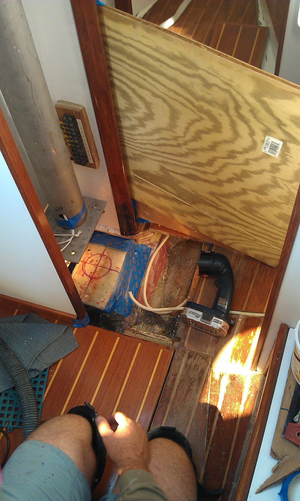
We began with a test fitting to locate the proper position for the compression post mounting plate.
After a bit of head scratching and calculations we marked the correct position. With the post hanging in the hole from above decks we charged ahead...
We taped off the deck step, created a electrical barrier between the aluminum mast sleeve and the stainless steel deck plate, fit the wooden centering puck on the post, ran messenger lines for mast electronics, and finally fit the base of the compression post onto the assembly.
Lowering the post down for another test fit we were discouraged to find the gap between the deck and the deck plate was in excess of 1/8". We designed the system to have a 1/32" to 3/32" inch gap between the deck and the deck plate. This gap will ensure the compression post bears the force of the mast load not the decks. A gap in excess of 1/8" meant the post was too long, or did it mean the step on the keel was to high? Cutting the post would require us to delay our installation while the post returned to the machinist. We could grind down the interior step and continue the fitting today. Bet you can guess our next move...
We rigged up some plywood and tarps in hopes of limiting the fiberglass dust inside the boat and began to grind down the interior step. This was a time consuming process that required a bit of grinding followed by a test fit. Then more grinding. Then another test fit. Then... and you get the idea.
By the time we were satisfied with the fit Anne and I were using a sheet of paper to feel for gaps. To be certain we did not leave any voids under the step we applied mold wax to the base of the post and a thin layer of thickened epoxy to the step.
The final installation of the post went smoothly. My focus was on the interior. Anne managed the topside installation,
In the final assembly the tiny gap between the plate and the deck was filled with 3M 5200.
We left the original hole in deck to allow for the installation of the post and to ensure the decks were not bearing the load. I created a 1 1/2" wood puck to center the post in the original mast partners and prevent any movement.
The puck is fitted snugly in the partners and bolted directly to the deck plate and mast sleeve.
Looking down on the deck step the two bolts that affix to the wood puck at visible inside the mast sleeve just fore and aft of the messenger lines in the image above. The lag bolts at each corner of the deck step are set into the 2" thick solid fiberglass deck platform.
We plan to install the rigging on the mast tomorrow and step the mast on Tuesday!