C'est la Vie is a 1966 Charlie Morgan 34.

Her home port is Everglades City, FL. Our typical cruising area is Southwest Florida, the Florida Keys, the Southeastern Atlantic Seaboard, and the Bahamas. We are C'est la Vie's third owners and purchased her in 2005. We continue to maintain and update this classic vessel. Please post any questions or comments about C'est la Vie or our travels via the comment links below.


Showing posts with label Tools and Tactics. Show all posts

Monday, July 1, 2013

Taste the Water!

“Taste the water!” My immediate reply to Anne’s excited cries of, “the bilge pump is running, the cabin sole is wet, the bilge is full of water!”

While focused on setting anchor in Cooper River before the next thunderstorm washed over us, Anne and I both heard the sound.  Anne described it as the splat from a bag of pasta falling to the floor.  I thought it was a paperback book striking flat on the cabin sole.  I went below to search out the origin of the sound, but my hasty scan yielded no culprit.  We both returned our attention to the dark bruise of a thunderstorm blotting out an ever growing portion of the southern sky.

Agreeing on a spot mid channel in 11 feet of dark brown tannic water, we fell into our well-rehearsed roles for anchoring C’est la Vie.  Anne took the helm and I went forward.  Everything seemed normal… anchor slipped off the deck, under my hands the windlass fed out chain, Anne reversed the boat to set the hook,  Anne silences the engine and begins recording the data on our days travels, I rig the anchor bridle.  The routine derailed when Anne informed me the bilge pump cycled on.  Typically C’est la Vie is a very dry boat and the bilge pump rarely runs.  After a nearly a week of on and off rains, I figured some water had found its way inside and wandered on down to the bilge.  I do not recall my exact words, but I’m sure the sentiment was, “Thanks for the update on the bilge pump it is nothing to worry about.”

Anne slipped below and began to discover other oddities.  The bilge pump continued to run.  The cabin sole was wet.  She lifted a floor board and found standing water.  “Taste the water!” was my urgent reply to her alarmed cry for assistance.

For those unfamiliar with life aboard a boat… when living in/on a floating object there are two distinctly different types of flooding.   One: the gut wrenching, find the source or the boat will sink type of flooding where the hull is breached below the water line.  In this scenario salt water will continue to fill the boat until the hole is found and patched or the boat sinks.  Second:  Much less traumatic is the bummer we just lost our drinking, cooking, bathing fresh water due to a plumbing failure.   The fastest method of discerning the type of leak is… to taste the water.

My hand darted into the bilge and back to my mouth.  Fresh.  Whew, I tasted fresh water.  I rushed forward into a locker under the vee berth and closed the valve just downstream of the freshwater tank.  Unless the tank itself had failed this would stop additional water from leaking into the bilge.

Anne cleaning the bilges after the flood.
Anne followed the water up until she discovered warm water in the locker under the port side settee seats.  Warm water, port side my detective, plumber brain sifted the facts.  Donning a head lamp I scurried over the counter top to inspect the hot water heater.  Here I discovered the proverbial smoking gun.  The source of the leak and the unidentified noise heard on approach to the anchorage – the outlet hose on the hot water heater failed.  Anne focused on the cleanup, while I repaired the plumbing.   Within an hour the cabin returned to normal and our pressure water system was back on line.  Based on our estimates we lost 10 to 12 gallons of water.  Fortunately we carry an additional 10 gallons in jerry cans.  This isolated reserve water proven it value on multiple occasions.

This episode reinforced two best practices on board:  First, don’t’ put all your eggs in one basket.  Always carry additional potable water separate from the primary tank.  Second, turn off the vessel’s pressure water system if everyone departs the boat.  If we had not been on the boat to turn off the breaker for the fresh water pump, then the system would have pumped the entire contents of fresh water tank into the bilge.

Oh, and that thunderstorm looming to the south? It dissipated over Savannah providing us with only a brief shower. 


All is well that ends well.

Thursday, May 16, 2013

Re-installing Deck Hardware on the Cabin

Anne and I spent the day re-installing the hand rails, turtle, and dodger on C'est la Vie's freshly painted cabin.

Previously all C'est la Vie's deck hardware was affixed via wood screws into the cabin top.  The construction of C'est la Vie's cabin top varies from solid fiberglass, to cored wood, to layers of fiberglass with a void in between.  I feel relying on wood screws into a varied fiberglass buildup is a bad idea.  While stripping the hardware off the deck I decided to use through bolts when re-installing the deck hardware (the snaps and dot fasteners on the dodger went back in with wood screws.)

This process began prior to painting the decks.  I drilled out and filled each hole through the cabin top with thicken epoxy.

prepared to fill bolt holes for the turtle, handrails, and dodger.
This process had the added benefit of marking the location of each fastener from below.

We began today with simplest task - re-attach the handrails.  With only two fasteners per rail.  These gave us a good practice for working onward to the turtle and dodger.

I operated below decks and Anne stayed topside.  I began each install by drilling pilot holes through the old screw location.  Anne then confirmed the fit and give me the ok to drill out the holes to the proper diameter.  

We used butyl tape to seal the holes.  This required Anne to slightly countersink the exterior of the bolt hole, before wrapping the bolt in butyl tape and setting it in place.

Anne countersinking holes for the port forward hand rail. Note roll of butyl tape at her feet.
Once in place we worked as a team to tighten down the hardware.

Anne using a combination of  a large phillips head and a box end wrench to tighten down the through bolts.
Using this system the handrails went in place relatively quickly.  The turtle, with 12 fasteners to hold it in place took more time and effort, but the system was largely the same.  

Looking aft from forward right to back - hand rail, turtle (raised area resting on wood strip), and dodger (raised canvas that serves as windshield in foul weather, the "glass" is covered to prevent UV damage when not in use.)
 We through bolted the two primary hinge points of the dodger frame.  Each hinge plate requiring two bolts.  The rest of the cabin top dodger attachment points are either dot fasteners of snaps on which we did revert back to wood screws into the fiberglass.

Below decks the backing plates, washers, and nuts from the deck hardware are visible.  This seems a small price to pay for peace of mind when standing atop the turtle to furl the main, white knuckling onto the dodger frame in breaking waves, or placing one foot against the hand rail to coil the main halyard as C'est la Vie heels over making 6 knots in a good breeze.  We do have plans to incorporate the fasteners along the starboard  side turtle into a wooden grab rail below decks, but the will have to wait.  Currently we are looking forward to shoving off the dock and enjoying the view out across the freshly painted cabin top.

Looking out across the cabin from the cockpit.
The fresh paint and non-skid on the cabin trunk highlight the poor state of our decks.  Hopefully by the end of hurricane season 2013 we will have the deck refinished.  

Photos documenting the entire process can be found at...  Painting the Cabin Trunk - Spring 2013

Wednesday, May 15, 2013

Solar Panel Installation


The addition of a photo-voltaic (PV) system to C'est la Vie has long resided on our wish list.  Thanks to Ben V., an friend and co-worker who's previous profession was solar installations, for providing the expertise to jump start this project.  We ordered two Sunmodule 80W panels and a BlueSky Solar Boost 2000E charge controller from altE. The size of the panels was a compromise between energy production and mounting space.  I'm certain many cruisers are faced with the same delimia... want / need bigger panels, but lack suitable mounting options.

The equipment arrived in early March.

About a month ago I installed the BlueSky Charge Controller in the electrical panel.

BlueSky Charge controller is on the upper right of image

Then progress on the PV system installation took a back seat to painting and the cabin sole refinishing.  With the painting & refinishing projects nearly astern, we are now directing our efforts back to PV system.  Next step... mounting the two panels.

Our original FRP Bimini, installed in June 2010 (see Fitting Day For the New Bimini) held up well, but was beginning to show it's age... one ripped back corner the result of an accidental jibe and a couple cracks along fittings at the gallows.  All told we are very pleased with the performance of the FRP and elected to replace the bimini with a new sheet, $38 for a 4' x 8' piece at Lowes.  Experience taught us the best way to cut the material is with a fine tooth circular saw for long straight cuts, a hole saw for circles, and a dremel tool with cut off blade for short precise cuts or broad arcs.  

We used the old bimini as a template for the new.  Once the centerline of the new bimini was secured to the frame via conduit clamps (see image below), we placed the solar panel on top and debated the best options for mounting.

The new bimini quickly took on a swiss cheees look as we cut out access points for the solar panel installation


We decided to screw the forward panel frame directly to the wooden gallows.  The rear section of the panel is attached directly to the bimini frame via two conduit clamps.  The FRP bimini is also attached directly to the solar panel frame via machine screws & nuts along the leading edge.  Facilitating access to all the fasteners required five cut outs on each side of the bimini.

Port side bimini & panel installation from below.
From below the only noticeable difference are the cut-outs and the addition of two conduit clamps along the rear frame.  One pair of 10ga wires for each panel will exit the bimini and snake down to a through deck fitting, but that is tomorrow's project.

From above the panels' only shade will come from the mainsail.  Unfortunately the panels are not adjustable to track the sun, but outfitting a cruising boat is all about compromises.

The view from above.  The only shade will come from the mainsail.
From afar the panels are relatively obscure and do not add clutter to C'est la Vie's profile.

The starboard panel from afar.  The installation adds little windage or profile clutter beyond already existed from gallows and bimini. 

The panels will add to the difficulty to securing the mainsail boot.  Due largely to the boom gallows and the cut of our new mainsail, I do not feel the panels will be in any danger from the main sail hardware or sheet.

We created a photo album to document the PV project... Solar Power - Spring 2013


Tuesday, May 14, 2013

Cabin Sole Refinishing - installing floor hardware

Since returning to Florida, the majority of our efforts have gone towards completing the installation of Lonwood Marine Flooring on the cabin sole.  Save for re-installing the trim we have completed the galley & salon area.

Looking aft at new flooring in the salon & galley. 
This section of flooring had two weeks of dry time while we traveled to North Carolina.  Over the past couple days, I  trimmed the edges at the floorboard joints and installed the floor hardware.

Floor hardware?  Well this includes a recessed finger handle for each floor board and a strike plate for the bulkhead mounted table leg (both visible center, right in image above.) 

After finding the ideal location for each floor board's handle, I began the installation by using a 1 1/8" paddle bit to auger out a depression for the center of the handle.  The circular center is the deepest portion of the handle. While the large diameter hole is only partial depth, the I did ensure the paddle bit's center point did pierced the backside of the flooring. The small hole will prevent water from pooling under the handle. 

I began the floorboard handle installation by drilling out the center section.

With the center drilled, I then used calipers to mark the location of the hinge portion of the handle.  The hinge is the second deepest portion of the handle.  A razor knife and chisle were used to excavate the flooring material. 

using the handle to mark off material to be removed.
At this stage the base plate of the handle rest flush on the new flooring and could be used to trace out the remaining area to be removed.  The thickness of the new flooring nearly matched the thickness of the handle plate so in most areas only the new flooring was removed to recess the baseplate.


Once the handle fit neatly into the recess, four #8 counter sink screws hold it in place.

Previously only two of C'est la Vie's five removable floor boards contained  recessed handles.  We plan to install a handle in each section.

With the area aft of the main bulkhead complete, we are onto making templates and cutting flooring for the forward area.

back to creating templates and cutting flooring.
  
 We plan to glue the remaining flooring down tomorrow morning.

Tuesday, April 9, 2013

More holes to fill in the cabin trunk

The application of a second coat of epoxy to the gallows wooden crosspiece began the day.

Two coats of epoxy on the gallows.
My plan is to build up three coats of West Systems Epoxy to seal the wood and then add 6 to 8 coats of Bristol Finish for the UV Protection.

Anne joined me for an afternoon of finding and grinding out small voids in the cabin trunk.  These voids, primarily found in the fiberglass layer below the gelcoat, date back to the original construction and are caused by a failure to completely fill the mold with epoxy.  Fast forward 47 years and these voids, the largest the size of a small pea, are causing the ordinal blue gelcoat layer and the paint applied in 1997 to crack. 

Anne uses an awl to identify in mark voids.  I used the grinder to open them up.
Today we expose the voids.  Tomorrow, weather permitting, we will fill the voids with thicken epoxy.


The number of voids we discovered was surprising, but better to fix them now than be forced to go in after our new paint has dried.  Fortunately the vast majority of the voids are on areas to which we plan to apply Kiwi Grip Non-Skid. This will make the task of fairing the area much easier.

More images from this project can be found in - Painting Cabin Trunk - Spring 2013

Hope the weather holds...

Monday, April 8, 2013

Filling Holes in the Cabin Top (a.k.a. dig a hole then fill it up.)

Today was devoted to filling holes in the cabin top.  Most were small holes used for fastening the dodger, the turtle, and the handrails to the cabin.  


never realized the cabin roof had so many holes.
I drilled the partial depth holes out to 1/4" diameter.  Holes for fasteners that may receive great stress loads (i.e. dodger frame, turtle, and handrails) I expanded to 1/2" and drilled through to the interior of the boat. This will allow us to through bolt and install backing plates on critical hardware. 


the interior view . ready for epoxy
All this drilling made a horrible mess of both the interior and the topsides of C'est la Vie.  The shop vac and I teamed up to clear away fiberglass and wood core.  Next I sealed the interior holes with tape.  Using a syringe and thicken epoxy I filled all the holes.  After painting the topsides we will come back and redrill the holes for the hardware. Drilling through the over sized epoxy plug will prevent water from ever reaching the wooden core of the cabin top.

The other hole in the cabin top took a bit more effort to fill.


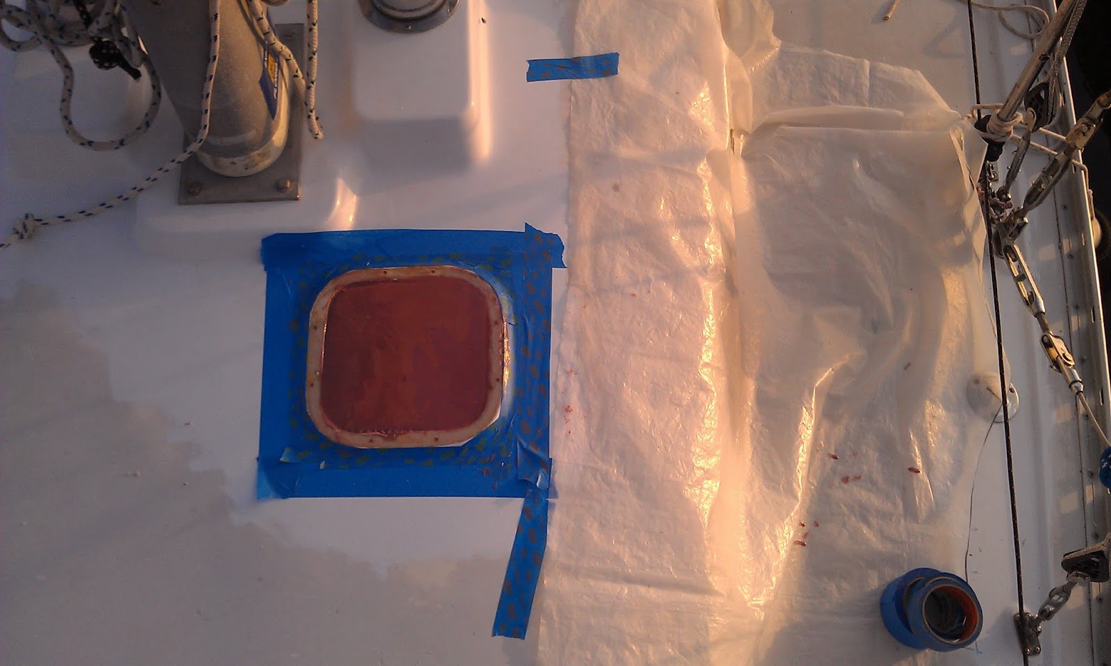
The broken and leaking hatch in the head must go.
C'est la Vie's small head hatch was added by her second owner.  The additional light and ventilation are beneficial.  A few years ago the hatch began to leak around the frame.  Last summer, while loading the dinghy on deck we broke the hinge on the hatch.  Now we have opted to replace the hatch with a Nicro 2000 Solar powered vent fan.

Fortunately the screws retreated easily from the deck and frame.  Unfortunately the hatch was bedded with 5200 and refused to let go.

the proper tools for removing 5200.
The 5200 succumb to a heat gun, a scraper, and a hammer.  I then sanded down the area to remove the remaining 5200 and created another giant mess inside the boat... shop vac to the rescue.

Using clear plastic sheeting I created a template for the outside dimensions (OD) and the inside dimensions (ID) of the opening.


creating templates for material to fill and cover the opening.
I plan to use sea teak for the exterior material. So the OD dimensions were transferred to the material. 


 the fan will rest upon sea teak on the topsides
Fortunately I have some scrap teak to use for the deck plug and interior material.   Fitting the teak plug took a few trips between the hole and the sander, but patience paid off in a snug fit.  


the teak plug will be visible from below decks.
When flush with the interior cabin ceiling the 3/4" thick teak plug did not fill the entire depth of the deck.  One layer of  3/8" Plascore brought the plug nearly flush with the deck.  I filled the remaining voids with thicken epoxy.


Now we await for the epoxy to cure.  Addition photos of this project are available in the photo album titled -  Solar Vent Fan Install - Spring 2013.

Saturday, April 6, 2013

Sewing new bug screens for hatches

Our existing hatch screens, made by Anne over 7 years ago, grew threadbare.  So now it is my turn to sew the hatch screens.  

With all the Outward Bound Staff departed we utilize the large spaces in the Sunset Island Lodge as work areas. 


The west end of the dining room converted to sewing loft.
 Having ample space to lay out projects is incredibly helpful.  For this endeavor a portion of the dining room became the sewing loft and the salon floor a space to draft out patterns.  

I utilized plastic sheeting for the pattern material.  Patterns represent the "no-see-um" screen portions of the hatch covers.  Due to it's light weight I find the screen difficult to work with so patterns assist with the layout and cutting. 


Basic geometry - a framing square, a straight edges, a 3' piece of string, and a tape measure were used to create the patterns.    
Fortunately C'est la Vie's two hatches are square.  The center hatch frame measures 22" x 22".  To leave ample room for operating the hatch, I created the pattern based on a 24" square.  The forward hatch measured 20" x 20" thus I used 22" for the pattern.  

Each hatch screen consists of two panels of "no-see-um" material.  The curved section wraps around to form the sides and back of the cover.  The rectangular  section follows the arc of the leading edge of the hatch as it moves from a close to open position.
   
Two patterns - the upper two panels are for the smaller forward hatch,  The larger patterns in the fore ground are for the  center hatch.
I use two sided tape to join and test the patterns.  Satisfied with the fit, the patterns are laid atop the screen and weighted down to hold the pattern and fabric stationary and wrinkle free while cutting. 

Ready to cut the screen.   Battens, straight edges, and a square are used to hold the fabric &  pattern stationary while cutting.
Attempting to cut clean edges on the screen is futile.  I hide all the edges of the screen in the finish product.  

For joining the screen sections prior to sewing, I use two sided basting tape (I gave up on pins a long time ago.)


joining the two screen sections with basting tape.
The screen material is too flimsy to securely hold stitches.  My solution is to use 1" nylon webbing as binding tape on the screen to screen seams.  This method has the added benefit of hiding those rough edges on the screen.


finally time to begin sewing.

We own a Sailrite LZ-1 and purchased a 1" binding tape attachment along with the machine.  This attachment is a must have in my opinion. Similar attachments are available for most machines.  

To more easily differentiate between to hatch screens, I used yellow binding tape on the center hatch and blue tape on the forward hatch. 


filling tubular webbing with lead cast net weights.
Tubular webbing filled with lead cast net weights serves as the ballast in base of the hatch screen. The lower edge of the screen and the weighted webbing are hidden inside a Sunbrella base.


the long sunbrella base sections.  
Since the sunbrella is a heavy fabric and the base sections are simple in shape, I did not create patterns for these pieces.   

Sewing base proved more complex than I originally speculated. Initially the two sections of the sunbrella base were sewn onto each side of the screen (i.e. interior & exterior.)   Next I tacked one end of the weighted tube onto the sunbrella base.  Finally I joined the two bottom edges of the base.


test fitting the final product.
Can't say I'm eager for a buggy night at anchor, but at least we are a bit more prepared.

More images from this project are available in the Hatch Screens - Spring 2013 photo album.  


Friday, March 1, 2013

Slowly brushing forward on the interior brightwork

Nearly one month has passed since my last post.  I made steady progress on the interior wood in the first couple weeks of February.

Before and After...  four coats of Bristol Finish
Work commitments and rainy days have slowed down the progress in late February.  

I have chosen to use Bristol Finish on the interior wood.  We use Bristol Finish on the exterior wood and are typically pleased with the outcome.  Using the same product on all C'est la Vie's wood reduces the number various chemicals we need to carry aboard when traveling.   For the interior wood I am applying three coats wet on wet, allowing the finish to dry completely, sanding with  220 to 400 grit paper, and then applying a final top coat.


A galley cabinet door with the final coat drying.
I prefer to work on trim, drawers, and cabinet doors that are easily removed outside the boat.  Since we have quite a few bugs here in the Everglades, I typically set up a large screen tent as an outside work space.

Starboard salon cabinetry and trim ready for the first three coats.
 Much of the trim work either refuses to budge or is simply easier to refinish in place.  

I hope to commit a few full days to the trim and cabin sole in early March. 

Tuesday, October 2, 2012

Have You Checked Your Hose Clamps Recently?

One of the few items remaining in C'est la Vie's engine compartment is the drive shaft.  The drive shaft is a solid stainless steel rod that connects the engine inside the boat to the prop outside the boat.
C'est la Vie's shaft and shaft seal were replaced in 2007 
 Traveling from the prop towards the engine, the point where the shaft passes through the hull it is supported by shaft log.  The log is a bronze tube with rubber bushings.  The log relies on water from outside the hull to serves as a lubricate thus reducing wear and friction. Directly forward of the log is our shaft seal.  The shaft seal allows the shaft to spin freely yet prevents water from entering the boat.   In 2007, we replaced the shaft, shaft log, and the shaft seal (here is a link to the photo album - Replace Shaft, Log, and Seal - fall 07) 

During the 2007 project, we purchased a PYI-PSS shaft seal and had the boat yard complete the installation work.  The shaft seal uses a rubber bellows as a spring to press a carbon flange against a spinning stainless steel rotor.  The carbon flange and stainless steel rotor are very smooth and when pressed together create a water proof seal.  As with any hole in the hull of the boat a failure of this system can cause the boat to sink.
the newly installed shaft seal - Fall 2007
Since all the components of the shaft system were new in 2007, I left them in place and did not intend to replace any parts.  My experience over the weekend has me questioning this decision.

C'est la Vie's Shaft Seal - Sept 30, 2012
While sanding between coats of primer in the bilge, I noticed a paint drip on the aft most of the shaft seal's four hose clamps.  Using a scotch bite scrubbing pad, I reached back to remove the paint drip.  Instantly the hose clamp broke in my hands. 

the  stainless steel hose clamp that broke in my hands after 5 years of
service on our shaft seal.
 Alarmed I grabbed a nut tool and attempted to loosen the other hose clamps for an inspection.  The very next hose clamp I touched, the forward most clamp, broke as I torqued on the hex head.  Yikes!  Failure of this clamps can sink the boat.  The clamps used on shaft seal were provided by the manufacturer, but are not of the quality I expect for critical through hull fittings.   Not all hose clamps are created equal.  

Without a doubt all hose clamps on board a boat should be stainless steel, but even among stainless clamps there is a broad spectrum of quality.  Clamps used in critical areas (i.e. through hull fittings, engine coolant lines, engine exhaust lines, black water systems, etc.) must be ABYC approved  316 stainless steel with a non-perforated band.    
an ABYC approved 316 SS hose clamp with a non-perforated bans will replace
the bands on our shaft seal.
How does one identify the various quality of clamps?  The easiest test is to run a magnet across all hose clamps on the boat.  If the magnet is attracted to the clamp then the clamp contains ferrous metal that will easily rust. Any clamp attracted to a magnet needs to be kicked off the boat ASAP.  I keep a magnet in my tool box expressly for testing hose clamps, bolts, screws, etc.  If any of these items do not pass the magnet test then off they go.

Hose clamps that will pass the magnet test are appropriate for non-critical boat systems (i.e. tank vent lines, fresh water plumbing, etc.).   If the clamp is destined for a system that is considered critical then it must pass two additional tests.  First is the band non-perforated?  A non perforated band is stronger, better resists rust, and provides more uniform pressure around a hose.  Secondly the hex head on the clamp must be 7mm.

I'm unsure if the 7mm hex head is a brand specific standard or if it is set by the ABYC.  All high quality AWAB Hose clamps have a 7mm head so I look to this as an identifying feature of high quality clamps.

If your using the 7mm head as standard of quality then I recommend purchasing a  flexible shaft 7mm nut tool  to compliment the clamps.  

It is worth noting an exception to my hose clamp rant.  As hose diameter increases to 2" or greater and/or if the hose has a wire for additional strength (e.g. engine exhaust systems), then t-bolt hose clamps are recommended due to their ability to provide increase pressure on the hose.  

Monday, May 21, 2012

Marking Control Lines on C'est la Vie


 While Anne piloted us ever northward along the ICW, I took advantage of the mellow conditions to properly mark the reefing lines on C’est la Vie’s mainsail.   To aid in efficiently reducing sail, it rarely seems that enlarging sail area is done under pressure, we mark the reefing lines at the cleat on the boom.  The first reef line receives a mark for the full sail and for the reef point.  The second reefing line receives a mark for the full sail, the first reef, and the second reef point. 
mainsail reefing lines marked with indelible ink
Initially we make the marks using a sharpie marker.  After a couple months of sailing and assessing the position of marks it is time to properly mark the line with some whipping twine.

Marking with whipping twine has the advantage of being both easy to see and easy to feel.  When working at night or under duress feeling the marks saves time and effort.

The tools required are scissors and a sewing awl.  Using a high quality whipping twine will enhance the quality and longevity of the marks.  

Resources with quality directions on whipping line can be found on the internet, example - Finish Whipping Method 1.  Look around and pick your favorite.

A hint for finishing the whipping is to use a sewing awl to pass the ends of the twine through the line. Using the sewing awl, I pass the ends through the rope three to four times.  
passing the ends of the whipping twine through the rope
This trick keeps the whipping from unraveling and gives the mark a clean look without loose ends hanged about.
completed mark 
 We use this technique to mark various lines around C’est la Vie – reefing lines, halyards, dinghy painter,  topping lift, etc.

new marks on first and second reef lines.

Tuesday, May 15, 2012

Anchor Management - part 2


Part one of Anchor Management was posted on May 14, 2012

Third Step  - lets do this  already... Anne typically pilots C'est la Vie to the drop site using the MOB mark on the GPS in step two.  Once on approach I go forward and release the anchor so that it is hanging off the bowsprit inches above the water.  Optimally, C'est la Vie's velocity is nil upon reaching the drop site.  Anne and I have developed hand signals to communicate during this process (fodder for a future post perhaps.)  I release the anchor and watch for the subtle change in the speed of the chain across the roller to identify when the anchor strikes the bottom.  Once the anchor rests on the bottom, I slow the rate of the chain to match the speed at which C'est la Vie is moving away from the drop site.  Continuing to quickly drop rode would only serve to create a pile of chain on the bottom next to the anchor.  If the conditions don’t move C’est la Vie away from the drop site, then I signal to Anne to back away using the motor.

Our primary anchor rode consists of 100 feet of chain followed by 200 feet of ¾” braided rope.  Beginning at 40 feet, the rode is marked off in 10 foot increments.  On the chain section we use two zip ties passed through the links of chain.  On the rope section we use zip ties passed through the braid of the rope.  The zip ties vary in color.  If we lose count on the marks, then we refer to a list of marks written down in the cover of our log book.
Colored Zip Ties used to mark the length on the anchor rode
We typically anchor in water less than 15 feet so use of the rope section of the anchor rode is rare (scope 1:7 = 15 feet deep X 7 = 105 feet of rode.)  When setting the anchor on chain only rode we use a snubber line.  The anchor chain has no flex.  In rough or windy conditions C’est la Vie can pull violently against the anchor rode.  The lack of flex in the  anchor system can literally rip the windlass or cleats off the foredeck. .  The snubber line serves as a shock absorber between the chain rode and the cleats on the foredeck.

C’est la Vie’s snubber line consists of a 30 foot section of megabraid line with a chain hook spliced in the middle.   When the hooks is attached to the chain two 15 foot sections of line extend back towards the bow.  I always leave the snubber tied into one of the two bow cleats when working at the foredeck.  
Anchor deployed.  Snubber tied into port cleat ready to be set.
 To set the snubber,  I stop the chain when the appropriate mark passes the bow roller and is hanging in the air.  The secured end of the snubber line and chain hook, typically starboard side out of habit, is tied off to the bow cleat.  The remaining line and chain hook are then fed through the starboard bow fairlead.  The chain hook is affixed to a link of chain out beyond/below the bobstay.  With the chain hook in place the free end of the snubber line is then lead through the port side fairlead and made fast to the port side bow cleat with no slack in the line.   Next, I return to the windlass and continue to run out chain until a long bight droops past the chain hook, approximately 10 additional feet.  Now back to the port side cleat, I slowly release line until the chain hook is just above the surface of the water and then tie off line to the port side cleat.  Back to the starboard cleat, I now take in any slack remaining between the chain hook and the cleat. 

Snubber line set with chain hook at surface of water.
Writing out directions for setting the snubber line makes the process seem complex and time consuming,  it typically takes less than two minutes to accomplish and is essential when using a chain rode.  When completed the two legs of the snubber line act independently to secure the vessel to the anchor and to absorb shock loads when anchored in rough conditions.  The chain is secured at the windlass and serves as a back up should the snubber line fail.
Deck view of the rigged snubber line.
When anchoring in areas where the length of rode moves beyond our 100 feet of chain, the rope rode acts provides flex in the system and an snubber line is not required.  I tie the line off to both bow anchors and then run it back to the windlass.

Anchor tied off when depth required use of rope section of rode.
It is rare that Anne and I feel the need to use C’est la Vie’s engine to set the anchor.  If we are unsure of the holding or are expecting foul weather then we will use the engine to pull against the anchor prior to setting the snubber line.