C'est la Vie is a 1966 Charlie Morgan 34.

Her home port is Everglades City, FL. Our typical cruising area is Southwest Florida, the Florida Keys, the Southeastern Atlantic Seaboard, and the Bahamas. We are C'est la Vie's third owners and purchased her in 2005. We continue to maintain and update this classic vessel. Please post any questions or comments about C'est la Vie or our travels via the comment links below.


Wednesday, October 10, 2012

Mounting engine room components on the sound proofing

With the sound proofing installed what to do with all the engine room wiring, plumbing, filters, etc that must be attached to the walls...?

chaos of wiring on the engine compartment wall.  Fuel filter is mounted on right
The sound proofing panels are 1" thick.  My solution began by creating 1" thick starboard spacers with a 1/4" hole drilled in the center.

drilling 1/4" holes in 1" thick starboard

Using a band saw to cut out the spacers

Most of the spacers created were 1" squares.  I did create larger spacers specifically for the fuel filter.
Using 1/4" thick starboard, I created  mounting boards for various engine compartment components

starboard side mounting board for electrical wiring & light
 With the mounting boards and spacers in hand I returned to the engine compartment.  Using a razor knife I cut out 1" squares in the sound proofing and inserted the spacers.  The spacers were then taped over to protect the foam and hold the spacer in place.  I then drilled the panels and walls to line up with the holes in the spaces and secured the entire assembly with #10 machine screws.  Using #10 screws in 1/4" spacer holes gave me some wiggle room on lining it all up.

starboard side mounting board in place.  Clockwise from top - wiring bus for misc, engine room light, negative post, and primary positive house bank  fuse.

The image above is the same area as pictured at the top of this post. A similar yet less crowded panel is located on the port side wall.  The fuel filter and engine room blower are mounted directly on 1" spacers.


Next up is to re-install the housing, straps, and wiring for the four house bank batteries.

Monday, October 8, 2012

Sound Proofing - part 2

The installation of the sound proofing on the aft, port, starboard, and ceiling of the engine compartment is compete.  The work took more time than anticipated, but that is par for the course in the boat world.  I am pleased with the aesthetics of the sound proofing.  Between the white of the new bilge paint and the reflective silver color of the sound proofing panels, the engine room appears quite bright and smartly institutional.

port side of engine compartment sound proofing installation complete.
The final paragraph of sound proofing part - 1 attempted to briefly describe the mechanical fasteners used to affix the sound proofing.  I fear my words fell short, and since a picture is worth one thousand words here is a couple of images to describe the process.

installing sound proofing mounting pins on the engine room access panel

  The mounting pins are available in self adhesive or screw on (pictured above).  Trusting the mechanical fasteners over the adhesive, the majority of the pins I used were the screw in type.  The self adhesive model proved essential in some of the hard to reach crannies of the engine room.

the foam panel pressed onto the mounting pins.
Once the pins are in place the pre-cut foam panels are pressed onto the pins.  The point of the pins easily pass trough the panel and extent out the face.   The pins are then cut flush to slightly proud of the surface of the panel.  Caps that grab the pins are pressed on to hold the panel in place.

The port side engine access completed
The installation instructions mandated one pin for every square foot of panel and tape around the perimenter.  I used well beyond that number of pins in the hatches and on the ceiling.  The hatches required additional pins due to the inability to secure the perimeter of the panel with tape.  Gravity dictated additional pins in the ceiling.  I used far less than one pin per square foot on the port, aft, and starboard walls because many of the engine components attached to the walls and the tape around the perimeter of the panels serve to secure the sound proofing.


Sunday, October 7, 2012

Sound Proofing the Engine Compartment

C'est la Vie's previous sound proofing consisted of a low density, 1/2" thick paneling.  The paneling was likely installed she was re-powered in the mid nineties.  I've never felt that the paneling was effective at reducing the sound and it was definitely showing it's age by showering the compartment with paper like flakes whenever touched.  Prior to painting the area I removed the old paneling with a hammer and scraper.

removing what remained of the old sound proofing panels

The boat yard assisted me in picking out and ordering new sound proofing material.  The new material is 1" thick and consists, from the face inward, mylar (or similar) outer coating, 5/8" open cell foam, 1/8" lead, and 1/4" open cell foam.  It ships in 24" X 54" sheets.  Along with the foam, I ordered the mounting hardware.

I used cardboard to create templates of the various engine compartment walls.  This allowed me to minimize waste material and create accurate panels without damaging the sound proofing material.  This process began with recording measurements in my journal and then transferring the dimensions to the cardboard laid out on a work table outside the boat.
from sketches in my journal I created the cardboard templates

Once the cardboard was cut into the basic shape, the panels were test fit in the boat.

Starboard side test fit.  The white blocks  with bolts are 1" thick mounts for the fuel filter.  These blocks will allow the fuel filter to be mounted without damaging the sound proofing
The fitting took multiple trips between the boat and the work table.  Each test fit, I made notes and sketches on the templates as to the necessary modifications.  Once pleased with the fit, the next step was to transfer the dimensions of the template onto the new sound proofing.
From cardboard to foam.

I began with the largest pieces first and then used the smaller templates to  figure out how best to minimize waste material. The installation directions recommended that for longevity of the material the edges be taped over prior to installation.

To protect the foam from damage, I taped over the exposed edges.
Some brands of sound proofing offer double sided panels (mylar face on both sides).  These panels cost more, but it is worth consideration.  The backside should never be exposed to water, but you never know what is going to happen "out there."


The time spent on templates ensured a proper fit of the material on the first time. The panels are held in place  by mounting pins that affix to the walls.  Once screwed to the walls via a wide back plate the pins pierce the foam.  A cover plate / washer is then pressed on the pin and secures the panel.  The edges are taped into place.

Next step - create and install mounting panels for the engine room electronics and lighting.


Saturday, October 6, 2012

Engine Haul Project - week two update

Here is the week two progress report...

I completed the repairs to the port side battery shelf and added a strip of 4" wide fiberglass mat along all the joints in the engine compartment.  The bilge and engine compartment are now painted - two coats of primer and two coats of Interlux Bilge Kote.

Before:
One week ago...

After:
repairs and painting in the bilge and engine compartment complete
Ironically,  I completed the repairs and painting while working around the shaft and couple only to remove them once the paint dried.  Removing the shaft, shaft couple, shaft seal, prop, and cutlass bearing were time and energy consuming projects this week.  These adventures are highlighted in a previous update - Project Creep Sets In On The Engine Haul. 

Here is the run down on the drive system:

  • The shaft and couple are visiting the machine shop for a "facing"
  • A PYI-PSS service kit for shaft seal is on order
  • A new cutlass bearing is on order
  •  Prop is scrubbed and polished

 The exterior of the water lift muffler received a couple fresh coats of paint.  Using 1/2 plywood I created a new shelf for the water lift muffler.  To seal the new muffler shelf and the existing shelf for the bilge pump float switches, I applied four coats of epoxy to each.

clockwise from the back - refinished water lift muffler, shelf for  bilge pump float switches; shelf for muffler
The engine received a second coat of  red prior to Mike, the diesel mechanic, arrival this week.  Upon his arrival we continued the tear down of the engine.

clockwise from the top - engine, transmission, and fly wheel
Base on the age of the engine - 16 years and the run time - 2800 hours, Mike suggested to:

  • Inspect and clean the heat exchanger core - We removed the core. Now it is my task to clean the core and the fresh water channels in the engine block
  • Test and tune the fuel injectors - I dropped them off at Coastal Diesel Service in New Bern.
  • Replace the drift plate - linkage between engine and transmission - part ordered
  • Replace the rear seal - keeps engine from leaking into the fly wheel housing.  Not an anticipated repair , but we discovered some oil around the fly wheel.
  • Replace motor mounts - No surprise here.  The new mounts are on order.


A sure sign you're in deep?

left - heat exchanger core needs cleaning
right - prop recently scrubbed and polished
When your heat exchanger core and prop are hanging out together on a table beside the boat.

I'm off to the boat to install the new sound proofing while I await the arrival of serviced and new engine parts.


Here is a link to a photo album of the entire project - Haul Engine - Fall 2012


Thursday, October 4, 2012

Project Creep sets in on the engine haul - arrgh!

After discovering the alarming state of the shaft seal hose clamps (see post - Have you checked you hose clamps recently?), I reviewed the installation data on the PYI-PSS Shaft Seal and learned that they recommend the replacement of the bellows every 6 years.   Well we are currently at the five year mark and replacing the bellows requires pulling the shaft couple or the prop and rudder. Since only the shaft couple stood between me and the replacement of the bellows, I ordered an new bellows and set to removing the couple on the shaft.  The couple (pictured below) links the shaft to the transmission on the engine.  Two set screws secure the couple to the shaft. How hard can it be?

3/8" stainless steel bolts connect the puller on left and the shaft couple on the right
The boatyard loaned me a puller and a small copper sledge hammer.  I spent three cramped and sweaty hours coaxing the couple off the shaft.  Pullers and shaft couples now reside in my nightmares.  In the end persistence won out... 
shaft attachments from left to right (or stern to bow) - shaft seal bellows with hose clamps above; carbon rotor of shaft seal; stainless rotor of shaft seal; and couple with set screws above
I presented the liberated couple to the boat yard staff along with the borrowed puller and hammer.  The boat yard then informed me of the need to "face" the couple prior re-installation.  Facing the couple requires a metal lathe to clean up any irregularities in forward surface.  Couple in hand I set off to the machine shop where I was informed that facing the couple also required the shaft.  And back to the boat...

Ever supportive, the boat yard staff now loaned me a prop puller.  Fortunately the prop succumb to removal efforts in under an hour.


Shaft in tow, I returned to the machine shop.  Noting some wear on the shaft, Fred, the machinist, knitted his brow as he inquired as to the age of the shaft.  We replaced the shaft five years ago.  The wear on the shaft was isolated to the section of the shaft in contact the our cutlass bearing.  So with the encouragement of Fred and the boat yard staff, I set about removing the cutlass bearing.

Fortunately an overnight of rest separated my couple and shaft pulling from my cutlass bearing removal.

shaft long atop and cutlass bearing in my hand
Par for the course, the cutlass bearing required hours of effort and extreme measures to remove.  The shaft log is a bronze tube that lines the hole in the hull through which the drive shaft passes.  The cutlass bearing is a  bronze tube lined with rubber flanges that minimizes wear on the prop shaft as it passed through the log. Water serves as a lubricant in the cutlass bearing.  C'est la Vie's log is in good condition. We will replace the cutlass bearing.

We have now reached a point where every component of the engine and drive system are removed from the boat.  It is time be begin to rebuild!

More images from the project are available via our photo album - Engine Haul Project - fall 2012
  

Tuesday, October 2, 2012

Have You Checked Your Hose Clamps Recently?

One of the few items remaining in C'est la Vie's engine compartment is the drive shaft.  The drive shaft is a solid stainless steel rod that connects the engine inside the boat to the prop outside the boat.
C'est la Vie's shaft and shaft seal were replaced in 2007 
 Traveling from the prop towards the engine, the point where the shaft passes through the hull it is supported by shaft log.  The log is a bronze tube with rubber bushings.  The log relies on water from outside the hull to serves as a lubricate thus reducing wear and friction. Directly forward of the log is our shaft seal.  The shaft seal allows the shaft to spin freely yet prevents water from entering the boat.   In 2007, we replaced the shaft, shaft log, and the shaft seal (here is a link to the photo album - Replace Shaft, Log, and Seal - fall 07

During the 2007 project, we purchased a PYI-PSS shaft seal and had the boat yard complete the installation work.  The shaft seal uses a rubber bellows as a spring to press a carbon flange against a spinning stainless steel rotor.  The carbon flange and stainless steel rotor are very smooth and when pressed together create a water proof seal.  As with any hole in the hull of the boat a failure of this system can cause the boat to sink.
the newly installed shaft seal - Fall 2007
Since all the components of the shaft system were new in 2007, I left them in place and did not intend to replace any parts.  My experience over the weekend has me questioning this decision.

C'est la Vie's Shaft Seal - Sept 30, 2012
While sanding between coats of primer in the bilge, I noticed a paint drip on the aft most of the shaft seal's four hose clamps.  Using a scotch bite scrubbing pad, I reached back to remove the paint drip.  Instantly the hose clamp broke in my hands. 

the  stainless steel hose clamp that broke in my hands after 5 years of
service on our shaft seal.
 Alarmed I grabbed a nut tool and attempted to loosen the other hose clamps for an inspection.  The very next hose clamp I touched, the forward most clamp, broke as I torqued on the hex head.  Yikes!  Failure of this clamps can sink the boat.  The clamps used on shaft seal were provided by the manufacturer, but are not of the quality I expect for critical through hull fittings.   Not all hose clamps are created equal.  

Without a doubt all hose clamps on board a boat should be stainless steel, but even among stainless clamps there is a broad spectrum of quality.  Clamps used in critical areas (i.e. through hull fittings, engine coolant lines, engine exhaust lines, black water systems, etc.) must be ABYC approved  316 stainless steel with a non-perforated band.    
an ABYC approved 316 SS hose clamp with a non-perforated bans will replace
the bands on our shaft seal.
How does one identify the various quality of clamps?  The easiest test is to run a magnet across all hose clamps on the boat.  If the magnet is attracted to the clamp then the clamp contains ferrous metal that will easily rust. Any clamp attracted to a magnet needs to be kicked off the boat ASAP.  I keep a magnet in my tool box expressly for testing hose clamps, bolts, screws, etc.  If any of these items do not pass the magnet test then off they go.

Hose clamps that will pass the magnet test are appropriate for non-critical boat systems (i.e. tank vent lines, fresh water plumbing, etc.).   If the clamp is destined for a system that is considered critical then it must pass two additional tests.  First is the band non-perforated?  A non perforated band is stronger, better resists rust, and provides more uniform pressure around a hose.  Secondly the hex head on the clamp must be 7mm.

I'm unsure if the 7mm hex head is a brand specific standard or if it is set by the ABYC.  All high quality AWAB Hose clamps have a 7mm head so I look to this as an identifying feature of high quality clamps.

If your using the 7mm head as standard of quality then I recommend purchasing a  flexible shaft 7mm nut tool  to compliment the clamps.  

It is worth noting an exception to my hose clamp rant.  As hose diameter increases to 2" or greater and/or if the hose has a wire for additional strength (e.g. engine exhaust systems), then t-bolt hose clamps are recommended due to their ability to provide increase pressure on the hose.  

Saturday, September 29, 2012

Refurbishing Engine Compartment and Bilge

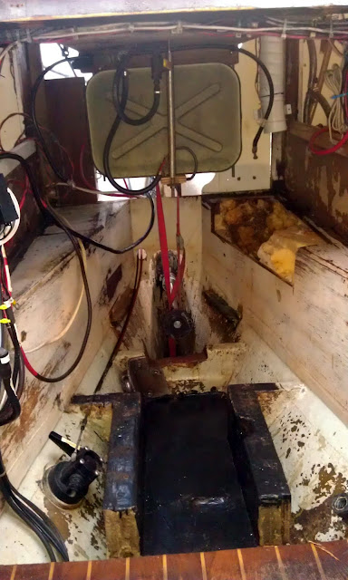
Once the engine, batteries, decaying sound proofing, battery acid soaked shelf, a miasma of hoses, and a gallon of bilge muck were exorcised from C'est la Vie the engine compartment bilge lay bare.
C'est la Vie's engine compartment and bilge laid bare
 The pie shaped shelves (right and left in the image above) are where we store the four, 6 volt batteries that make up our house bank.  The previous owner spilled battery acid on the port side shelf.  In an attempt to forestall the damage, we bathe the area in a baking soda solution about once a year.  Despite our efforts the 1/2" plywood in the effected area continued to decay. I removed the damaged section (on right in image above.).  The sound proofing panel in the area also suffered damage and is now gone.

 I constructed a replacement for the damaged shelf out of 1/2" plywood.
Test fit for shelf repair and prep for fiberglass
The base of the shelves are tabbed to the hull with  fiberglass mat.  Above the hull joint, bronze ring nails secured the joinery work in this part of C'est la Vie.  I'm using 4" wide fiberglass mat to secure the battery shelf repair so why not reinforce all the joints in the area with strip of mat.  This will make the entire assembly much stronger and hopefully add additional structural integrity to our already stout hull.

Along with the shelf repair the inside corners and outside corners of the shelves are now  reinforced with fiberglass mat.
The next phase, sanding the lower engine compartment and bilge, put my meager contortionist skills to the the test.  I'm certain a future of squeezing into tiny boxes or passing my body through the head of a tennis racket is not in my future, but after hours of twisting and grunting the area is ready for a coat of primer.

The depths of the bilge with one coat of primer
To say I am pleased with the results would be an understatement.  From replacing  anchor rollers at the bow to varnishing the oar on the autopilot at the stern, almost every facet of C'est la Vie has received some attention during our seven years of ownership.  The exception was the engine compartment and bilge.  The daunting task of removing the engine to access the area proved too great a hurtle.  Now we have moved beyond the hurtle and I am pleased.

The engine compartment with two coats of primer
  Two coats of primer are done.  Two coats of bilge paint are forecast.  The next step will be to install new sound proofing panels on the walls.

Additional images of the progress are available via a web album dedicated to this project.  Here is the link to the album: Haul Engine - Fall 2012

Wednesday, September 26, 2012

Engine Haul-out week one progress report

One week ago C'est la Vie's Beta Marine engine left it's mounts and exited the vessel for the first time in over 15 years.  Progress on the engine is moving along in slow plodding steps.  Resting atop blocks and a pallet the engine took up residence along C'est la Vie's starboard side.

C'est la Vie with her engine resting along side.
The next step was to continue removing components that would be damaged by the pending de-greasing and power washing. I used tape to create labels for various connection.  I also took numerous images to serve as visual aids when I begin the reconstruction.
In the process of labeling and removing engine components prior to washing / de-greasing the engine

After washing and de-greasing, I went over the motor with a small wire brush in an effort to remove any lingering rust or flaking paint. To prevent future rust I applied Ospho to all the bare ferrous metal. The Ospho  dries to a black color.  The black areas in the image below clearly indicate were the metal had begun to oxidize.

ready for the first coat of new paint.
Through out this process I have left the oil and fuel filters in place to protect the orifices underneath.  The air intake, fuel pump attachment, and various other inlets are protected by tape.

first coat of paint on the engine.
The first coat of a paint went on thin to ensure the new paint and the old paint are compatible.  I'll now give the first coat 24 hours to dry.

Meanwhile inside the boat... I have reached a turning point in the battle of the bilge.   Everything is out of the boat and the area is clean.
C'est la Vie's engine compartment clean and vacant

Not it is time to begin re-installing, repairing, and upgrading.  Replacing port side plywood damaged  when the previous owner spilled battery acid is the next step.  Fresh paint and new sound proofing will soon follow.

Here is a link to the photo album documenting my progress - Haul Engine - Fall 2012  I will continue to add photos to the album as the project progresses.